ShaneAO Motor Control
The GUI to control the motors in ShaneAO is saomot_gui. It can be started from shanevnc, covert, shark, or shred with the command saomot_gui.Position and status of each motor are displayed in the GUI. It also allows one to either change the position of each motor individually or reconfigure using stored setups. The GUI with a typical setup is shown in Figure 1.
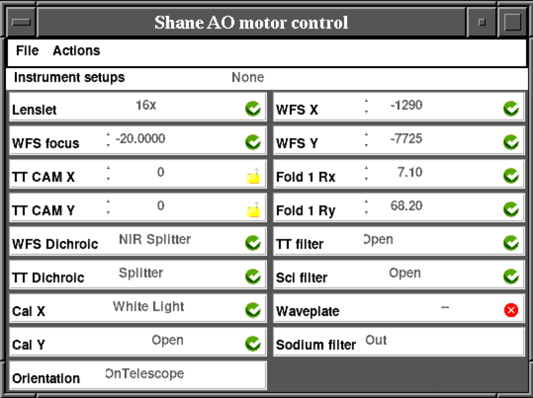
Figure 1: saomot_gui GUI
Each motor has its own control interface within the GUI and each works in a similar way. For motors with defined positions (e.g. Lenslet), click on the name of the position (e.g. 16x) and it will give you a menu of available positions. Simply click on the desired position and it will be shown with a yellow background and a green arrow will appear immediately to the right (Figure 2). The yellow background is a warning that the motor has not yet moved. To move the motor click on the green arrow.

Figure 2: Selection and Go Arrow
Many motors do not have predefined positions, for example the TT Cam X motor. To move these motors, enter the desired position in the entry box or use the up and down arrows to the left of the entry box to change the value (for example, the step size for the TT Cam X stage is 10 counts). Once you press the green arrow to move the motor, the icon will change from the green Ready check to a pie chart that will update from being all black at the beginning of the move to all green as the move completes. When the move is done, the icon will revert back to the green Ready check.
Other icons, shown in the table below, indicate the status of the motors. A red Error X indicates there is a problem with the motor motion. One can get more information about the motor by clicking on the icon, which will bring up a motor detail panel (see Figure 3). A yellow Warning triangle alerts users that there may be an issue, such as hitting a motion limit. Usually moving the motor again will clear the warning, but if not one can click on the icon to bring up the detail panel to get more information. A Lock icon indicates that the motor has been locked out to prevent use either due to a mechanical problem or because a staff member is doing maintenance on the mechanical stage or motor itself. The Gear icon is used to indicate that the stage is moving during calibration.
| Motor Status Icons | |||
|---|---|---|---|
| Status | Icon | Status | Icon |
| Ready/OK | Moving | ||
| Warning | Error | ||
| Locked | Calibrating | ||
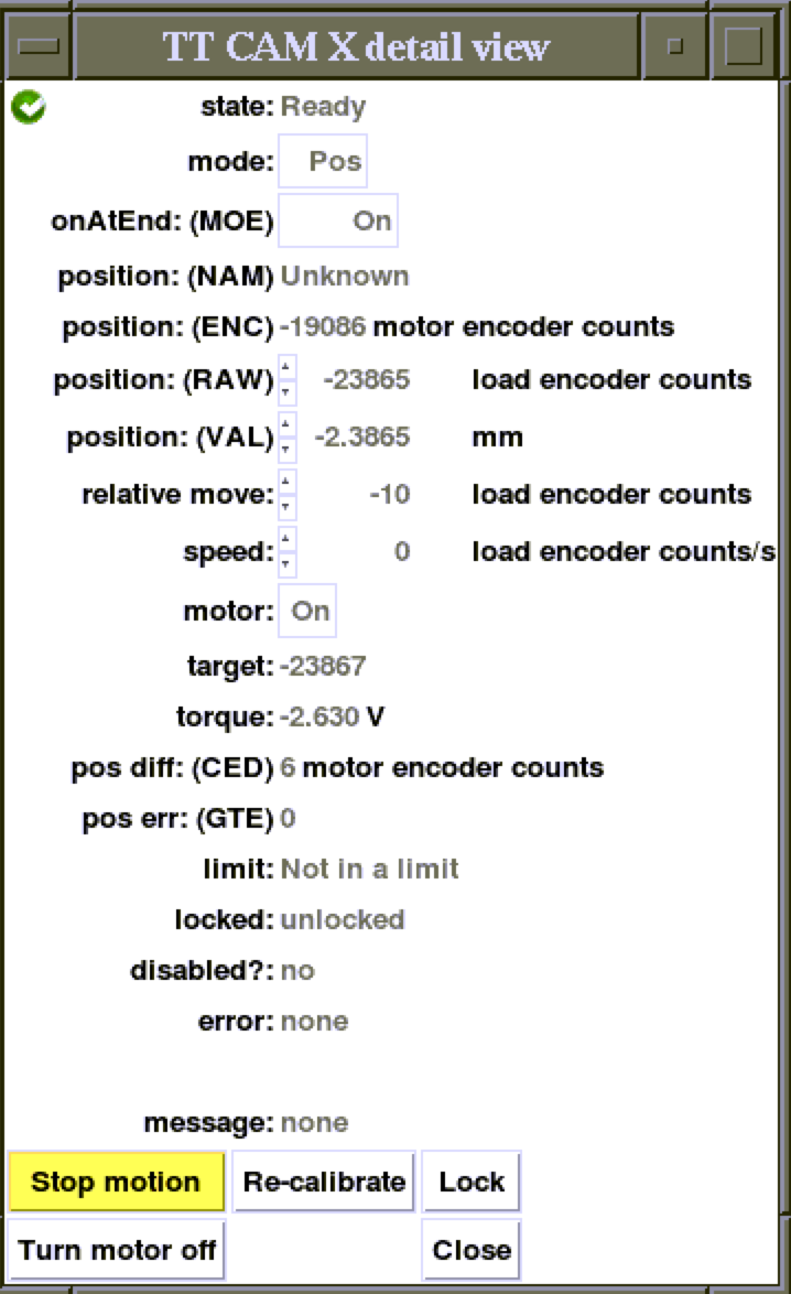
Figure 3: Motor Detail Panel
The detail panel (see Figure 3 for an example) shows detailed information about the motor and its status. From this panel one may change the operation mode of the motor or move it in absolute or relative moves. The buttons at the bottom of the window are all reasonably self-explanatory. The Lock button brings up a separate GUI (see Figure 4) to select which motors to lock out and an entry window to describe the reason for the lockout. Do not unlock a stage unless 100% sure that it is safe to do so.
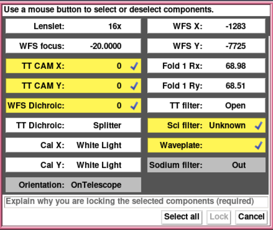
Figure 4: Lockout GUI
File Menu
The File menu enables one to change the font size of the GUI. This can also be done with the shortcuts Ctrl + to increase the font size or Ctrl - to decrease the font size. One can also quit the GUI from the file menu or by using the shortcut Ctrl q.
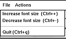
Figure 5: File Menu
Actions Menu
The Action menu has many options for interacting with the motors. The top section has two options to Cancel pending motor moves or Apply pending moves. This is handy when many stages need to be moves to change between Instrument setups (see below) or when you want to cancel such a move. Instead of using the menu, once can use the shortcut Ctrl c to cancel pending moves, or Ctrl m to move the stages.The second section has options for Enabling Motion (useful when the saomot server has been restarted) or Calibrating the motors. When calibrating motors, one has the choice of calibrating just stages that are not currently calibrated, or doing all stages. (Note, at present there is a bug in the server code, so that calibrating all stages, does most but not all, so some may need to be done individually).
The third section is to deal with misbehaving or broken motors, as well as safety lockouts. In case motors are moving in ways they shouldn't (e.g. when not commanded to move, or not properly reaching the desired position), one can stop all motor motion by clicking on Stop all motion. Locking out software control of one or more stages can be accomplished by clicking on Lock stages... which brings up the Lock GUI (shown above in Figure 4). If stages have been locked out and are ready to be put back into service, motion control can be re-enabled by clicking Unlock all. Please note that Unlock all should never be performed unless one is 100% certain that it is safe to do so.
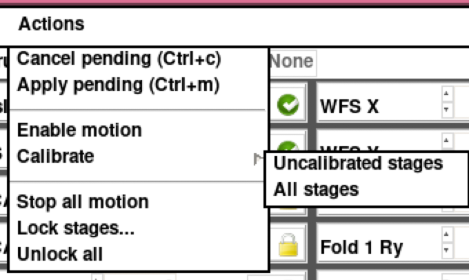
Figure 6: Actions Menu, inclusing Calibrate Sub-menu
Instrument Setups
It is possible to save setups for future use and for ease of switching between setups during observations. To get the instrument setup menu, click on the setup's name (default is None as shown in Figure 7). The menu initially has three items, Load setup file..., Choose directory..., and Save new setup.... Load setup file... will bring up a file browser and you can load an existing setup. Setup files for ShaneAO will always have the extension .shaneao. Choose directory... will also bring up a file browser window in which one can select the directory that contains the saved setup files. Once that directory is selected, the saved setup file names will be displayed in the top portion of the Instrument setup menu (as shown in Fig. 7). One can switch between setups by clicking on the desired setup then moving the motors (either individually by pushing the green arrow icons, or all at once using Actions-Apply pending, or with the keyboard shortcut Ctrl m.The last option, Save new setup..., brings up the Save Setup GUI (see Figure 8 below). By default, all movable stages are selected and highlighted in yellow. Click on a stage to deselect it if the value is not desired in the saved setup. Once the desired motors are selected, click on Save as..., which will bring up a file browser window in which the directory and file name for the new setup can be set.
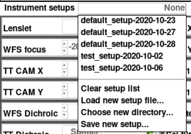
Figure 7: Instrument Setup Menu
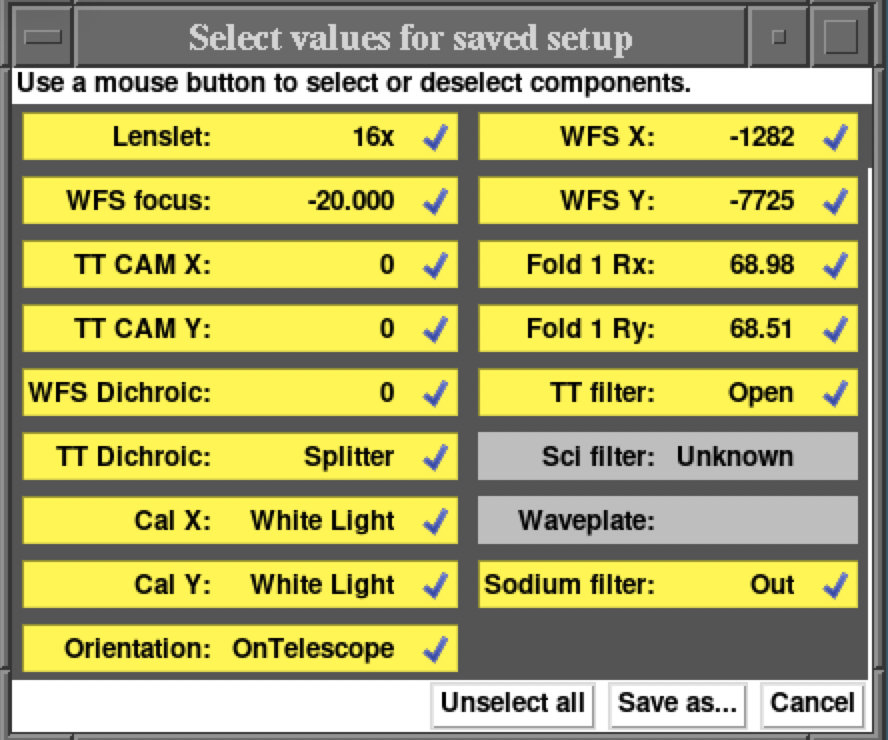
Figure 8: Save Setup GUI
Individual Motor Information
Details about each motor stage are described below.
Lenslet
The lenslet stage has three positions, 8x, 16x, and 30x, corresponding to lenslet arrays with 8, 16, or 30 lenslets across the telescope aperture. One can move to the 30x position, but those optics have not yet been installed.
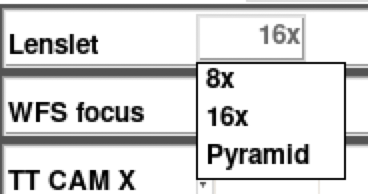
Figure 9: Lenslet Selection
| Lenslet Motor Technical Specifications | |
|---|---|
| 16x Lenslet | Encoder=-1832 |
| 8x Lenslet | Encoder=-446002 |
| Pyramid | Encoder=444924 |
| Motor Encoder Minimum | -450000 |
| Motor Encoder Maximum | 492000 |
| Max Speed | 40000 cnt/s |
WFS Focus
WFS focus stage is normally at 4475 for NGS observations. In LGS mode, when closing the WFS loop on the laser, the WFS focus position is set with the help of the WFS Focus Tracking GUI.
| WFS Focus Motor Technical Specifications | |
|---|---|
| NGS Position | -20.0 mm Encoder=-200000 |
| Motor Encoder Minimum | -214000 |
| Motor Encoder Maximum | 370000 |
| Max Speed | 1000 cnts/s |
TT Cam X and Y stages
The TT Cam X and Y stages are used during LGS operations to position the TT camera on the tip/tilt star.
| TT Cam X Motor Technical Specifications | |
|---|---|
| On-axis Position | Encoder=4018 |
| Motor Encoder Minimum | -280000 |
| Motor Encoder Maximum | 210000 |
| Max Speed | 25000 cnts/s |
| TT Cam Y Motor Technical Specifications | |
|---|---|
| On-axis Position | Encoder=-23867 |
| Motor Encoder Minimum | -250000 |
| Motor Encoder Maximum | 250000 |
| Max Speed | 25000 cnts/s |
WFS Dichroic
The WFS Dichroic stage moves different dichroics into the beam to determine which wavelengths of light go to the WFS and the ShARCS NIR Camera. Currently there is only one dichroic beam splitter installed.
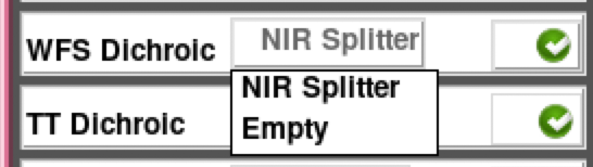
Figure 10: WFS Dichroic Selection
| WFS Dichroic Motor Technical Specifications | |
|---|---|
| NIR Splitter (900nm Dichroic) | Encoder=-6500 |
| Empty | Encoder=-12500 |
| Motor Encoder Minimum | -13000 |
| Motor Encoder Maximum | 2200 |
| Max Speed | 1000 cnts/s |
TT Dichroic
The TT Dichroic stage moves different dichroics or a mirror into the beam to determine which wavelengths of light go to the TT Camera. In NGS mode one will typically use the Mirror to send all the light to the WFS and no light will get to the TT Camera. In LGS mode, we use the Splitter, which is a 600 nm dichroic.
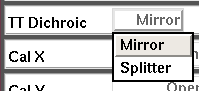
Figure 11: TT Dichroic Selection
| TT Dichroic Motor Technical Specifications | |
|---|---|
| Mirror | Encoder=-7403 |
| Splitter (600nm Dichroic) | Encoder=13010 |
| Motor Encoder Minimum | -26200 |
| Motor Encoder Maximum | 16700 |
| Max Speed | 1000 cnts/s |
Cal X and Cal Y
The Cal X and Cal Y stages control the positions of the calibration sources. Current sources are a White Light Source, Red Laser Source (635nm), and a Flea Camera (for field acquisition, if necessary). For strehl calibration using ShARCS, both Cal X and Cal Y should be in the White Light Source position. For science data acquisition, Cal Y should be in the Open position.
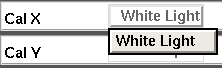
Figure 12: TT Dichroic Selection
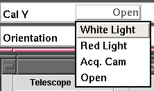
Figure 13: TT Dichroic Selection
| Cal X Motor Technical Specifications | |
|---|---|
| White Light Source | Encoder=-2865 |
| Motor Encoder Minimum | -38000 |
| Motor Encoder Maximum | 15000 |
| Max Speed | 2000 cnts/s |
| Cal Y Motor Technical Specifications | |
|---|---|
| Aquisition Camera | Encoder=-7625 |
| White Light Source | Encoder=1502 |
| Red Laser Source | Encoder=-1520 |
| Open | Encoder=8000 |
| Motor Encoder Minimum | -9200 |
| Motor Encoder Maximum | 8000 |
| Max Speed | 1000 cnts/s |
Orientation
Many motors in the SAO system have different motion parameters based on how the instrument is oriented as the TUB rotates and telescope moves. In general use, On Telescope should be selected. When SAO is stowed in the AO lab, select Stow(Z). For engineering tests, UserSet should be selected and the following saomot service keyword can be used to manually set the orientation: ORIENTATION. When ORIENTATION=OnTelescope, then OF_TOB, OF_DEC, and OF_HA come from poco (the 3-m telescope pointing service). If ORIENTATION=Stow(Z), it is the same as OnTelescope except Dec=37.3. If ORIENTATION=UserSet then OF_TUB, OF_DEC, and OF_HA keywords are user-writable, and used as if the bench is on the telescope and poco has those values.
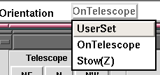
Figure 14: Orientation Selection
WFS X and WFS Y
The WFS X and Y motors are used for field steering in natural guide star (NGS) mode. Field steering range is about 20 arcsec in any direction. On-axis positions for the motors are X = -1290 and Y = -7725.These motors are rarely moved directly from the GUI, but rather through the fieldsteer GUI or dither scripts from ShARCS scripts.
| WFS X Motor Technical Specifications | |
|---|---|
| Motor Encoder Minimum | -83000 |
| Motor Encoder Maximum | 83000 |
| Max Speed | 5000 cnts/s |
| WFS Y Motor Technical Specifications | |
|---|---|
| Motor Encoder Minimum | -15688 |
| Motor Encoder Maximum | 3000 |
| Max Speed | 1500 cnts/s |
Fold 1 Rx and Ry
The Fold 1 Rx and Ry motors control the steering of light from the telescope into the ShaneAO instrument. Typical positions for the motors are X = 54.13 and Y = 61.78 (Note: GUI displays values that are Motor Encoder Counts / 1000.)
| Fold 1 Rx Motor Technical Specifications | |
|---|---|
| Motor Encoder Minimum | -17500 |
| Motor Encoder Maximum | 86000 |
| Max Speed | 2000 cnts/s |
| Fold 1 Ry Motor Technical Specifications | |
|---|---|
| Motor Encoder Minimum | -3000 |
| Motor Encoder Maximum | 93500 |
| Max Speed | 2000 cnts/s |
TT Filter
There is a Thorlabs filter wheel in front of the Tip/Tilt camera so that bright stars will not saturate the detector. Normal operations have the TT Filter in the Open position, but ND filters with Optical Density (OD) of 1, 2, 3, 4, and 5.
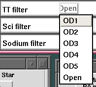
Figure 15: TT Filter Selection
| TT Filter Position List | |
|---|---|
| 1 | OD1 |
| 2 | OD2 |
| 3 | OD3 |
| 4 | OD4 |
| 5 | OD5 |
| 6 | Open |
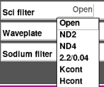
| Sci Filter Position List | |
|---|---|
| 1 | Open |
| 2 | ND2 |
| 3 | ND4 |
| 4 | 2.2/0.04 |
| 5 | Kcont |
| 6 | Hcont |
Sodium Filter
The Sodium Filter is installed in front of the WFS to block light from objects other than the Laser Guide Star. There are two positions, In and Out. A quirk of the system is that to move the filter Uplink in the shaneao (saocon_gui) code must be off. Hence, turn Uplink off, move the sodium filter, then turn Uplink back on.
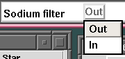
Figure 17: Sodium Filter Selection
Additional Info
There are six servers (dispatchers) that run behind the scenes for motor control. These run on shanevnc and are started as a group with the command ao start saomot. Individual servers can be started with the command ao start saomot1 (or saomot2, 3, 4, 5, or 7). One can stop all servers or just one using the ao stop saomot (or saomot1, etc.). The status of the servers can be seen with the ao status saomot command.There are 4 Galil motor controllers (saomot1, saomot2, saomot3, saomot7), a RIO controller (saomot4), and ThorLabs filter wheels (saomot5). The controller and channel for each motor is listed in the table below.
Communication to the Galils goes through a router named saorouter.ucolick.org. Communication to the TT Filter wheel is through the lantronix ao-serial-1.ucolick.org. Communication to the Sci Filter wheel is through the lantronix ao-serial-2.ucolick.org.
| Motor Control Channels | ||
|---|---|---|
| Motor | Dispatcher | Channel |
| Lenslet | 1 | G |
| WFS Focus | 7 | F |
| TT Cam X | 1 | F |
| TT Cam Y | 1 | E |
| WFS Dichroic | 2 | G |
| TT Dichroic | 2 | E |
| Cal X | 3 | A |
| Cal Y | 2 | F |
| WFS X | 7 | E |
| WFS Y | 7 | A, B, C |
| Fold 1 Rx | 1 | A |
| Fold 1 Ry | 1 | B |
| TT Filter | 5 | TTFILT |
| Sci Filter | 5 | SCIFILT |
| Sodium Filter | 4 | Digital 0 |
| Uplink TT Tip (X) | 4 | Analog 2 |
| Uplink TT Tilt (Y) | 4 | Analog 3 |
Last modified: Wed Jun 2 15:22:18 PDT 2021