PFCam Motor Control GUI
The PFCam Motor Control GUI (Figure 1) is used to control the science filter wheel, dewar focus, guider filter wheel, guider x-axis motion, as well as the top end functions of turning on and off the quartz flat field lamp, the moving the prime focus and the atmospheric dispersion compensator (ADC).The software is started on shard with the command
pfcam start gui
Each of the PFCam motors is controlled from one panel. Settings are selected or entered in each panel and movements are initiated by clicking the green arrow button (Figure 2) that appears when a desired position is entered. A motor position that is selected but differing from the current position will be designated with a yellow background. The status icons in each panel will display the current status of its related motor, e.g. green checkmark for move completed or in progress, pie chart percentage move completed (Figure 3), yellow triangle for a warning (Figure 4), red X for an error (Figure 5). The gray arrow icon indicates the direction and order of optics in the light path; a bar appears if the motor is in a position that might block the light path (Figure 4).
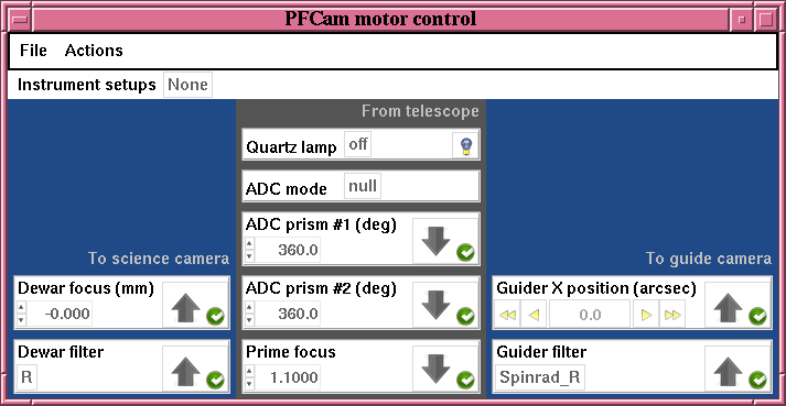
Figure 1: PFCam Motor Control GUI
 Figure 2: Selected positions that differ from the current motor position are highlighted in yellow and a green move arrow appears. |
 Figure 3: Piechart icon |
 Figure 4: Warning icon
|
 Figure 5: Error icon |
The "Quartz Lamp" flat-field lamps are mounted on the top of the prime focus ring. The lamps may be turned on by selecting "on" in its pulldown menu (Figure 8). Alternatively, clicking the light bulb icon toggles the lamp being on or off. When the lamp is on the light bulb icon will change to a lit bulb.
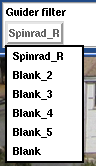 Figure 6: Guider Filter Menu |
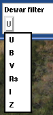 Figure 7: Dewar Filter Menu |
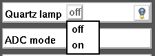 Figure 8: Quartz Lamp Menu |
The "Prime Focus" moves the entire optics barrel, which contains the two ADC prisms and the prime corrector plate, up or down for focusing the guide camera. This mechanism also affects the dewar focus, so the Prime Focus should always be set first and then fine focusing done with the Dewar Focus stage. The Prime Focus has a range of motion approximately from 1.1 to 4.0. Nominal focus is typically around 3.2. The small up and down arrows to the left of the entry box will change the displayed value by increments of 0.1.
The ADC has three modes of operation, selected from the "ADC mode" pulldown menu (Figure 9). During normal operations you will want to select "track" so that the ADC prisms move appropriately with position of the telescope to compensate for atmospheric refraction. Alternatively, if you desire not to use the ADCs, select "null" so that the ADC prisms will be parked in the appropriate position to not degrade imaging performance. "eng" mode is purely for testing the operation of the prisms or stopping their motion. When "eng" is selected you can move the prisms independently to any position via the "ADC prism #1" and "ADC prism #2" sections of the GUI.
The "ADC prism #1" and "ADC prism #2" sections work identically. Enter the desired angle of rotation into the entry box and click the green arrow to move it to the desired position. If the ADC mode is set to "track" or "null" the prisms will shortly (within two minutes) move to the appropriate positions on their own. The only way they will stay at the positions you command them if the ADC mode is "eng."
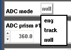
Figure 9: ADC Mode Menu
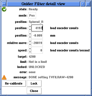
Figure 10: Motor Detail View
At the top of the motor control GUI is a menu bar with three options File, Instrument setups, and Actions, shown in Figures 11 - 13.
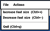 Figure 11: File Menu |
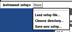 Figure 12: Instrument Setups Menu |
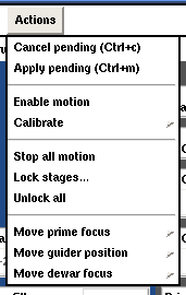 Figure 13: Actions Menu |
Under the File menu you can increase or decrease the font size or quit the GUI.
The Instrument setups menu allows you to Save or Load setups or choose a directory to search for saved setups. Selecting "Load" will bring up a file browser menu. "Save As" will bring up the window shown in Figure 14. Motors for which you want to save their positions for future use are highlighted in yellow. Clicking on a motor will toggle between selected and deselected (white background). Clicking the "Save As..." button will bring up a file browser window. Setups should be saved in your subdirectory in the observers directory of the user account.
Once a setup has been selected, the Instrument setup menu will have more options (Figure 15) including a list of the saved setups in that directory. If the instrument configuration matches a saved configuration, the name of that setup will be displayed in the Instrument setups bar (Figure 16).
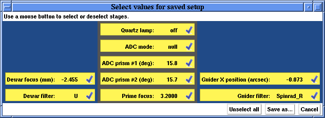
Figure 14: Save Setup Window
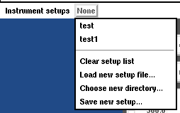 Figure 15: Setups Extended Menu |
 Figure 16: Instrument Setup Label |
The Actions menu has many options. "Cancel pending (Ctrl+c)" will remove all desired positions from the GUI and show the current positions of the motors. "Apply pending (Cntl+m)" is a convenient way to move multiple motors at the same time.
"Enable motion" will turn on motors and/or set them to their normal operating mode. If the motor is not calibrated when you enable motion, it will calibrate itself first. The "Calibrate" menu has two options (Figure 17), to calibrate only "Uncalibrate stages" or to calibrate "All stages."

Figure 17: Calibrate Menu
"Stop all motion" will stop all motors. Normally this option is only needed if something is not behaving as it should. "Lock stages..." brings up a separate window (Figure 18) and is used to lock out software control of the motors. This is usually done for safety reasons when a staff member is physically working on the instrument. "Unlock all" re-enables software control of the motors. Do not unlock stages unless you are certain it is safe to do so.
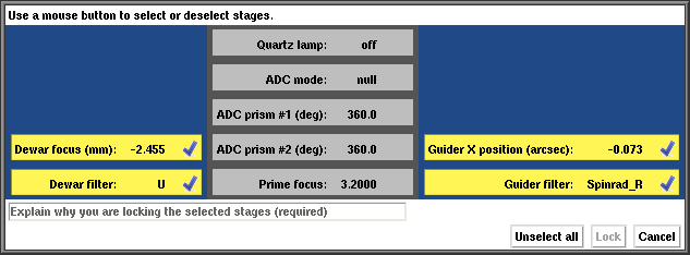
Figure 18: Lock Window
Three of the stages have predefined positions that one can move them to: Prime focus, Guider X position, and Dewar focus. The selections are shown in Figures 19-21, respectively.
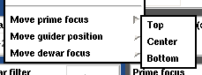 Figure 19: Prime Focus Defined Position Menu |
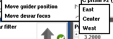 Figure 20: Guider X Position Defined Position Menu |
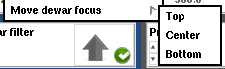 Figure 21: Dewar Focus Defined Position Menu |
Support Astronomers (sa@ucolick.org) Last modified: Fri May 18 12:18:10 PDT 2012