Optical/Motor Layout and Cabling
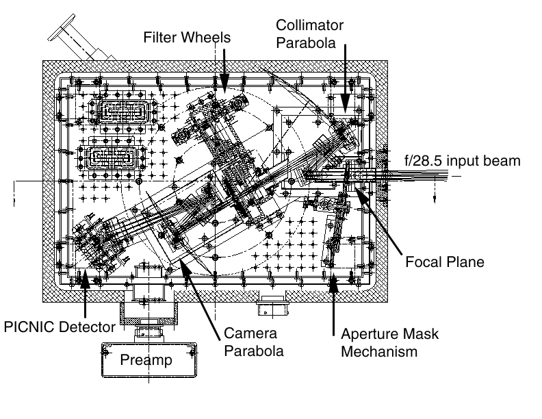
The lightpath and motors for IRCAL are depicted in the below diagram.

The following description is taken verbatim from James Graham's web site describing IRCAL.
IRCAL is a 1-2.5 μm camera optimised for use with the LLNL Lick adaptive optics system on the Shane 3 m telescope. Using diamond-turned gold-coated optics, the camera provides high efficiency diffraction limited imaging throughout the near-IR. IRCAL incorporates optimisations for obtaining high dynamic range images afforded by adaptive optics, coronagraphic masks, and a cross-dispersed silicon grism for high resolution spectroscopy.
DEWAR
The cryogenic and mechanical components of IRCAL were manufactured by IR Laboratories, Inc (Tucson, AZ), based on an liquid nitrogen cooled ND-8 dewar. By utilising a vapor cooled shield, the heat load on the liquid cryogen is very low, yielding a hold time in excess of 48 hours under normal conditions. There are three mechanisms inside the dewar: two filter wheels holding eight one inch diameter interference filters each, and a six position focal plane mask wheel. The mechanisms are driven with external stepper motors via mechanical feedthroughs. Light from the AO system enters on the right through a 0.85 inch diameter CaF2 window. The converging F/28.5 beam forms a focal plane at the aperture mask mechanism, is folded to the collimating parabola, and the collimated beam passes through a filter with a 5 degree tilt. The cold pupil stop is located on the far side of the filters, before the beam is focussed with the f/33 camera parabola, and folded onto the PICNIC focal plane array. The two optics boxes are shown baffling the pairs of parabola + fold flat, with baffle tubes in between.OPTICS
The optical design consists of two nearly balanced off axis parabolas with two folding flats. The camera optics reimage the AO corrected telescope focal plane, via a cold pupil stop (conjugate to the telescope primary mirror), to the IR focal plane array (FPA). There is a slight magnification from the F/28.5 output beam of the AO system to a camera focal ratio of F/33. This Nyquist samples the diffraction limit of the 3 m telescope at 2.2 μm. The measured plate scale is 75.6 ± 0.2 milliarcsec per pixel, giving a 19.4 arcsec field of view across the 256 x 256 pixel detector. A 5 mm pupil size was chosen as a compromise between instrument size, and the ability to do grism spectroscopy. With a 5 mm pupil, it is possible to do moderate resolution spectroscopy with a calcium fluoride and resin replica grating grism. R=700 is chosen to fit the full bandpass of the J, H, or K atmospheric windows across 256 pixels with 2 pixel spectral resolution.The mirrors are kinematically mounted on an Al optical bench that can be removed from the dewar as a single unit. The optical assembly can thus be aligned outside the dewar. Reference holes are machined in the optical bench, to which pinholes that define the optical axis are mounted. Using a laser, the optics can be aligned by adjusting the elements to pass the laser through the pinholes. As the entire assembly is made from homogeneous material, the alignment does not change as the optical bench cools from room temperature to 77K.
Two filter wheels and the pupil mask are housed in a filter wheel assembly box that mounts directly to the cold plate. The filters operate in the collimated beam with a 5 degree tilt to avoid optical ghosts. The wheels are spring loaded onto ruby balls for heat sinking. The mechanisms are geared with stainless steel bevelled gears, driven by stepper motors external to the dewar. The entire optical path is carefully baffled with housings over the optical elements and baffle tubes in between. The interior surfaces of the housings are sandblasted for surface roughness and anodised black. The interior of the baffle tubes are painted black.
The optical elements were manufactured by Janos Technology Inc in diamond turned aluminum and gold coated. Post polishing was performed by an IR Labs subcontractor.
Cabling
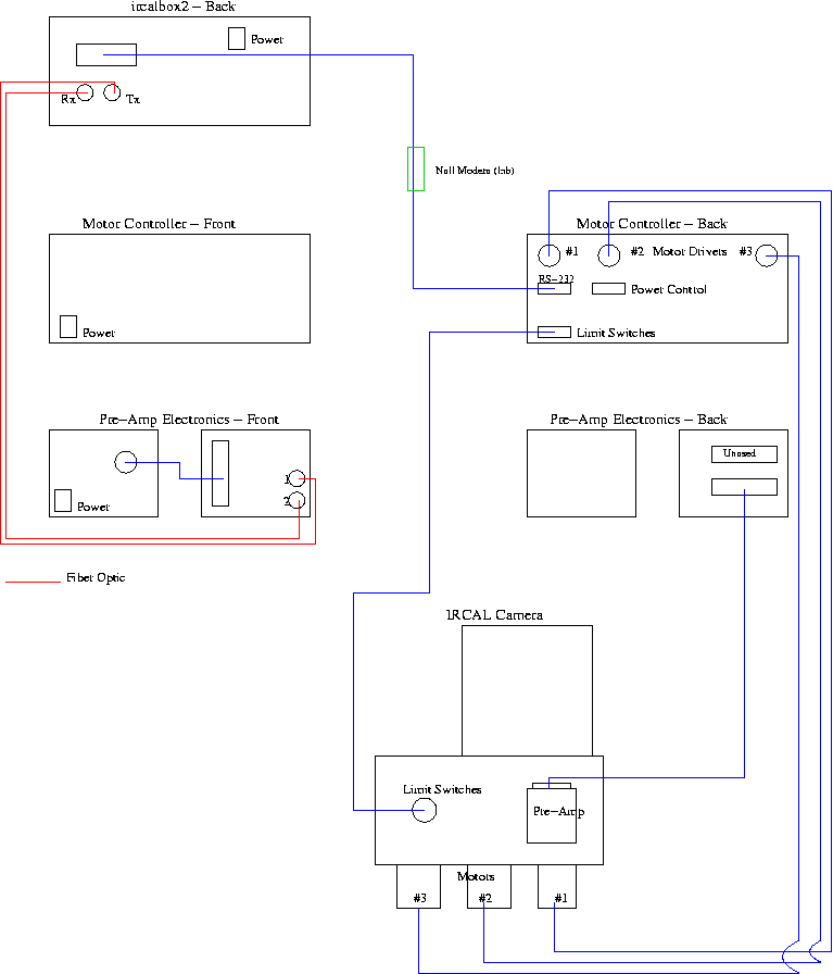
IRCAL should be set up according to the cabling diagram below. The view is a basic schematic for use by Lick technical staff.Please note that due to wiring difference, there must be a null modem installed in the serial line from ircalbox2 to the motor controller when IRCAL is in the lab.

Elinor Gates Last modified: Thu Jan 17 10:08:45 PST 2008