Hardware Overview
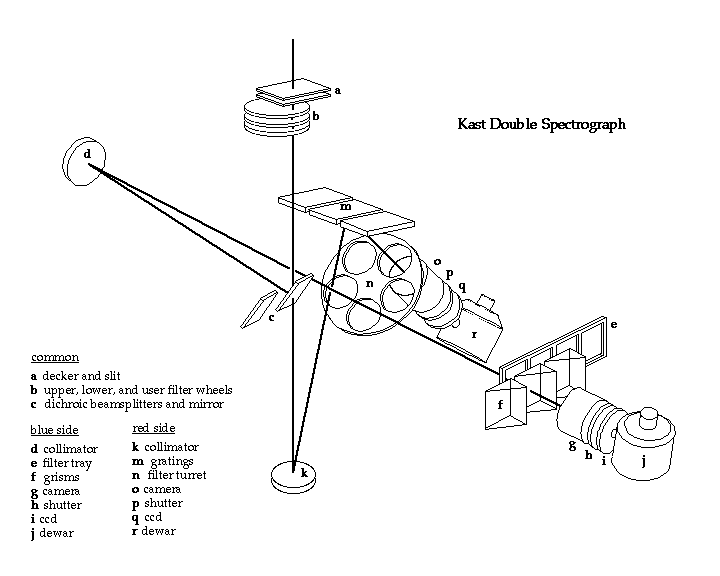
The converging light from the telescope is focused at the slit of the slit-decker assembly, and then passes through either the user filter module (consisting of three independent filter wheels known as the upper, lower, and user wheels) or the polarimeter module (containing two filter wheels and waveplate). These components are in common for both sides of the spectrograph. The beam then passes through a region where one of three possibilities may occur. The light can (1) strike a dichroic beamsplitter which passes the long wavelength light (the "red side") and reflects the shorter wavelengths (the "blue side"), (2) the light may strike an aluminized mirror which reflects all the light to the blue side, or (3) nothing can be in the beam, which allows all of the light to go to the red side. These options may be selected remotely. On the red side, after striking a silvered collimator, the beam proceeds to a reflectance grating and then passes through a filter wheel that can accommodate four filters up to 5.5-in. in diameter, and then goes on to the camera-shutter-dewar assembly. Any of three positions in the grating carrier can be selected and tilted by remote control, and the user may have either three gratings, or two gratings and a flat mirror (for direct imaging), mounted in the carrier. The blue-side light path consists of an identical but aluminized rather than silvered collimator, followed by a filter slide capable of holding three filters up to 4.5-in. in size. The light then passes through one of three remotely selectable grisms (or no grism for direct imaging work) and then to the camera-shutter-dewar assembly. This dewar is also mounted on an x-y stage, but since the Fairchild 2k x 2k CCD can record very nearly the entire useful spectral range produced by the camera, translating the dewar in the dispersion direction will not gain much. However, it is not uncommon to move the blue side stage in the x-direction in order to gain a hundred or two Angstroms at one end or the other. The shutters are quite close to the CCDs and are pretty light-tight with respect to the dome lights, at least. Schematic of the Kast Double Spectrograph
Note: The user filter assembly (b above), can be replaced with the polarimeter module.
Support Astronomers (sa@ucolick.org) Last modified: Sun Sep 18 14:28:17 PDT 2016