Kast Controller
|
The user interface for the Kast motor controller is started from user
account on gouda, shanevnc, or karnak by typing
kast start obs. You will be presented with a GUI as shown
Figure 1. The controller will display the current spectrograph motor
positions, and will allow you either to change the individual
parameters, or to reconfigure using stored setups. The GUI
communicates with the hardware via the dispatcher software. While
these dispatchers should always be running, there is a chance you will
have to start them as well. You can start the dispatchers by typing
kast start disp (and you may determine the status of the
dispatcher software with the command kast status). There is no
harm in trying to start the dispatchers if they are already running.
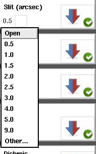
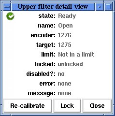
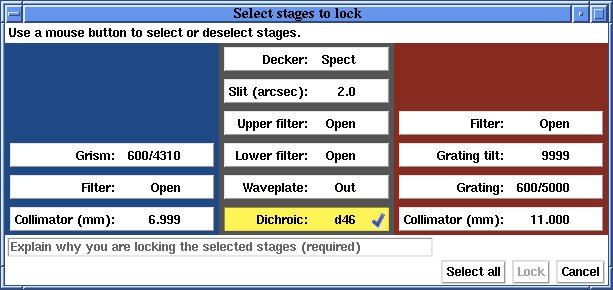
The Kast controller GUI may be stopped either from the File-Quit menu item or by typing kast stop obs. While there should be no need to ever stop the kast dispatchers, they may be stopped with the command kast stop disp. The spectrograph controller operates two separate galil motor controllers which work in parallel. Multiple stages on each controller may move at the same time. This means that if you want to change a number of items, you should not wait until one is done before requesting the next change. Make as many changes as you wish as quickly as you wish, and the controller will get it all done as soon as possible. The display will inform you what the status is of each item via the icons to the right of each stage's section of the GUI.The motors are divided into three categories based on where in the light path they are: Blue side (left section with blue backgroud), Common path (middle section with grey background), and Red side (right section with red background). Each motor has its own control interface within the GUI and each works in a similar way. For motors with defined positions (e.g. Decker), click on the name of the position (e.g. Finger) and it will give you a menu of available positions. Simply click on the desired position and it will be shown with a yellow background and a green arrow will appear immediately to the right (Figure 2). The yellow background is a warning that the motor has not yet moved. To move the motor click on the green arrow. The Collimators and Grating Tilt stages, do not have predefined positions. Enter your desired position into the entry box or use the up and down arrows to the left of the entry box to change the value (the default collimator step for the arrows is 3.0 mm and 1000 encoder counts for the grating tilt stage). The Slit and Waveplate stages have predefined positions but also have an Other... option (Figure 3) where you can enter your desired value (slit widths must be between 0.4 and 150 arcsec, waveplate rotation must be between 0 and 360 degrees). As for the predefined positions, the background will change to yellow and a green arrow will appear to the right of the entry box. Click the green arrow to move the motor. Status of the motors and instrument is shown with the icons to the right of each motor name. The red/blue arrows indicate the direction of the light path. If Kast is configured so that light is blocked by an optical element, then a bar will appear at the head of the arrow to indicate the issue (and arrows down stream of that blockage will vanish from the GUI) (Figure 5). A green circle with white check (Figure 4) indicates that the motor is ready and may be moved. A yellow triangle icon indicates a warning and that the motor has a minor issue. A red circle with white X (Figure 5) indicates that the motor is in an error state and should not (or can not) be moved. To get more information on the source of the warning or error, click on the icon and a detail panel (Figure 6) will appear. When a motor is moving you may get one of two icons (depending on the motor and its state). During normal operations when a motor is moving a black and green pie chart will appear showing its progress (Figure 4). During calibration of the motor an grey gear icon will show that the motor is moving (Figure 5). If software control of a motor is disabled (locked out) for safety, a padlock icon (Figure 4) will be displayed. Do not unlock a stage unless you are 100% sure that it is safe to do so.
|
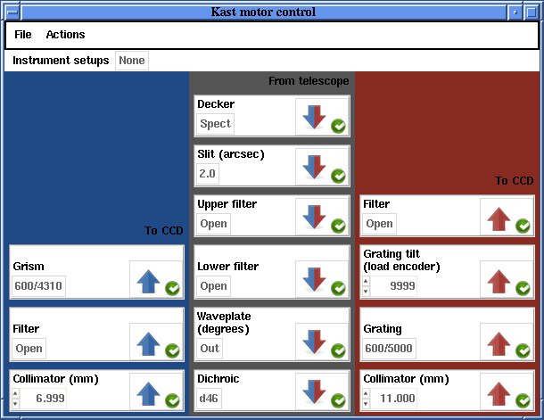
Figure 1: Kast Controller User Interface
Figure 2: Selection and Go Arrow
Figure 3: Slit width menu
Figure 4: Motor Moving and Lock icons
Figure 5: Motor Warning and Error icons
Figure 6: Detail Panel |
|
|
The menu bars have three options: File,
Actions, and Instrument setups. Keyboard shortcuts are also listed in the menus where
they are available.
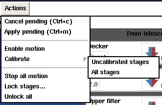
The File menu (Figure 7) lets you increase or decrease the font size as well as Quit the GUI. The Actions menu (Figure 8) has the following options:
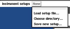
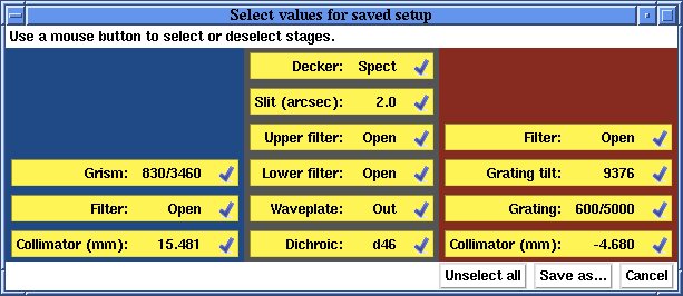
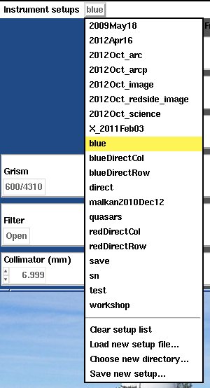
The Instrument setups menu (Figure 10) allows you to Load or Save motor setups, as well as Choose a directory for setups. The Load... option will bring up a file browser dialog where you select your saved setup. It will load in the data and you may either move all motors to the desire positions using Actions - Move all or move the motors using the green arrows in each motor section. The Save new setup... option allows you to save the currently displayed positions to a file for future use. You do not have to move the motor to the desired position to save it in a setup, it must simply be selected and displayed in the GUI. Once the desired motor positions are displayed, click on Instrument setups - Save new setup... and the Save Setup GUI will appear (Figure 11). By default all motors will be selected (yellow background) to be saved in the setup. You may unselect a stage by clicking on it (it will then have a white background). You may unselect all stages by clicking Unselect all. Once you have selected your desired stages, click Save As... to bring up a file browser dialog to name and save your file. Please save your setup to your subdirectory /u/user/observers/. Files saved elsewhere may be deleted or modified without notice. If you have existing setup files in your /u/user/observers/ subdirectory, you may select that directory using the Choose directory... option. When you click on Instrument setup you will have a list of existing setups to choose from (e.g. Figure 12). If the motor positions match an existing setup it will show that setup's name in the Instrument setup menu bar and highlight it in yellow in the setup selection list. You add the option to Clear setup list. |
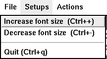
Figure 7: File Menu
Figure 8: Actions Menu
Figure 9: Lock GUI
Figure 10: Setups Menu
Figure 11: Save Setup GUI
Figure 12: Setup Selection Menu |


Support Astronomers (sa@ucolick.org) Last modified: Wed Jul 6 09:02:13 PDT 2016