Graphical User Interface
Starting the Graphical User Interface
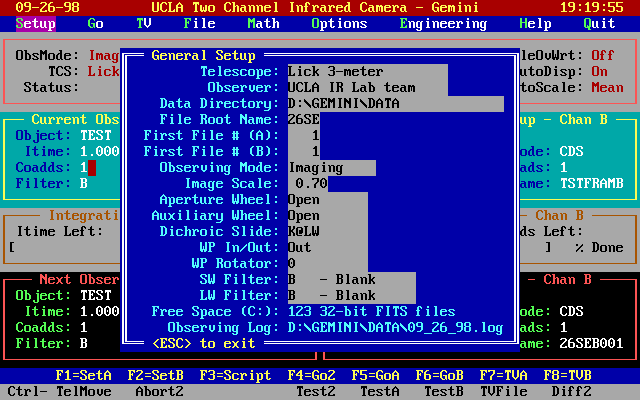
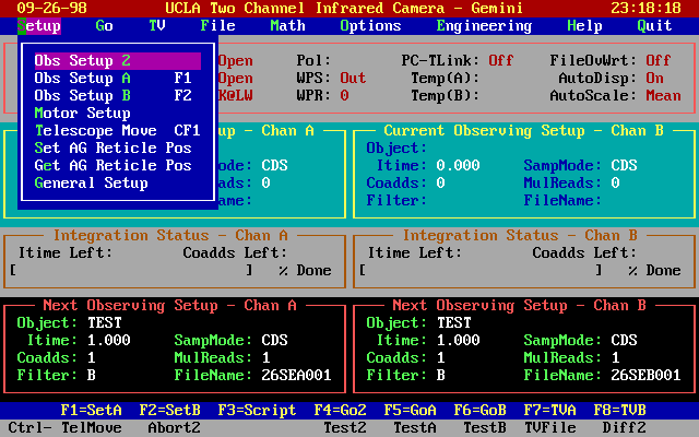
Setup Menu
Go Menu
TV Menu
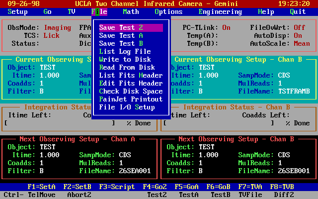
File Menu
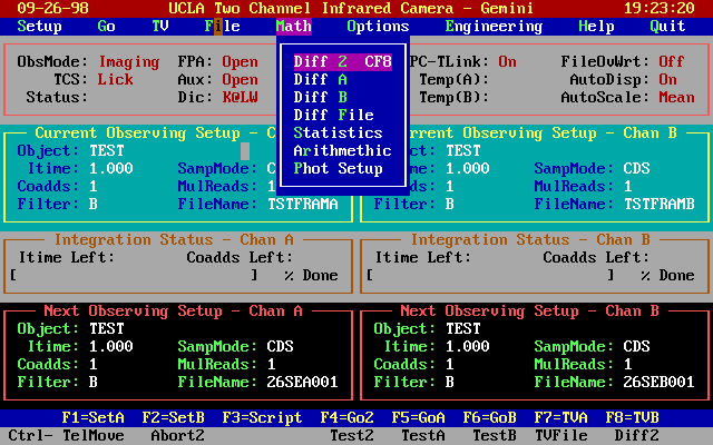
Math Menu
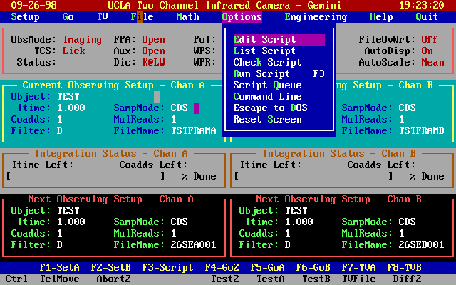
Options Menu
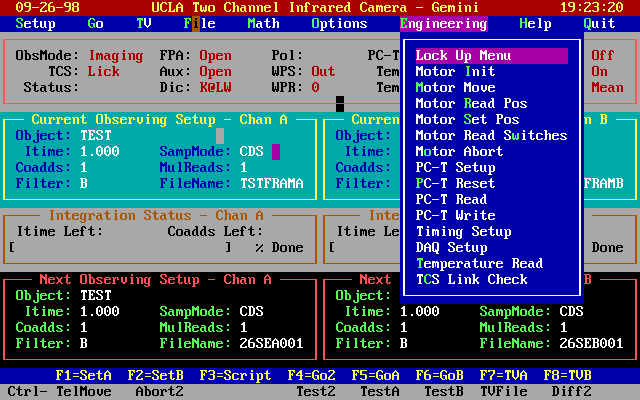
Engineering Menu
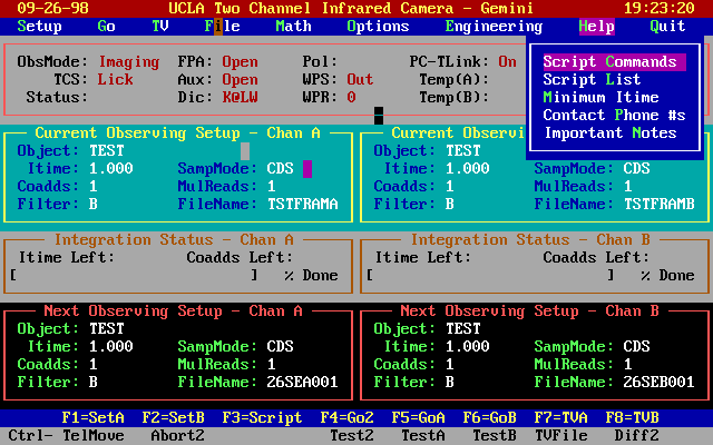
Help Menu
Motion Control
Image Display Screen
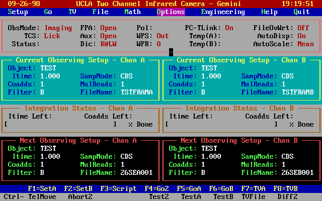
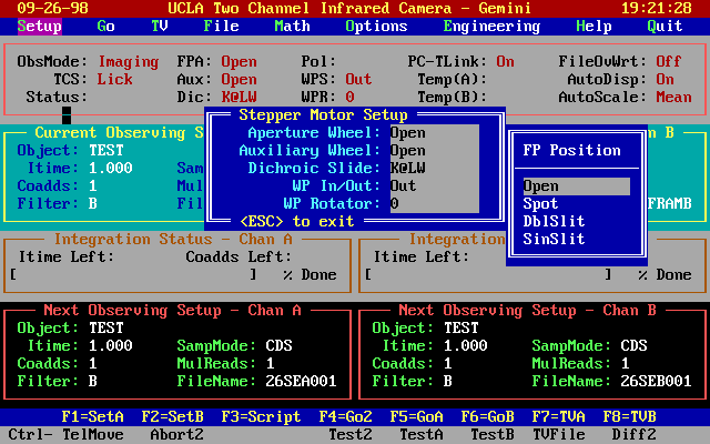
| ObsMode: TCS: Status: | Imaging,
Polarimetry, Spectropolarimetry Telescope control system interface, usually Lick Observatory If this area is blank, then no actions are in progress. If it is flashing "TV", then it means that control currently resides with the other (image) display terminal. |
| Focal Plane Aperture Wheel Status: Auxiliary Wheel Status: Dichroic Slide Status: |
Open (default), Spot, Long Slit, Double Slits Open (default), Polarizer, Calcite Prism K @ LW channel (default) or K @ SW channel |
| Polarizer: WavePlate Slide: WavePlate Rotation: | Calibrator; not
implemented Two positions, In or Out 0, 22.5, 45, or 67.5 |
The fourth column gives the status of the PC to transputer link (PC-TLink). Also displayed are the detector temperatures. NOTE: at present these are not updated by the computer.
The rightmost block in the status display area describes 3 "flags":
| FileOvWrt: | |
| If FileOvWrt = OFF, then you CAN overwrite existing files of the
same name. If FileOvWrt = ON, then the file protection is activated. | |
| AutoDisp: | = ON (default) means automatic display of each image. |
| AutoScale: | describes how the image display has been scaled. The default setting takes the MEAN of the data frame as an offset and then selects a gain which matches the lowest remaining signal to black and the highest signal to white. |
Current Observing Setup:
The fourth panel from the top (pale blue background - black border) displays the setup for the current observation. The left and right segments respectively refer to Channel A (the shortwave (SW) channel with the NICMOS HgCdTe array) and Channel B (the longwave (LW) channel with the SBRC InSb array).
These panels display the setup in current use or the integration that has just ended. The entries in these panels correspond directly to those in the lower black panel called NEXT OBSERVING SETUP. Changes to the observing setup are made in the lower panel only. We will return to this critical feature in a moment.
Integration Time Display:
Between the pale blue and the black setup panels is a graphical display which actively tracks the progress of the integration. A bar increases in length from 0% to 100% as the integration proceeds and a countdown display gives the Itime and Co-adds remaining. This countdown is a timer and does not perfectly reflect the overhead required for multiple readout modes; occasionally this overhead will cause the display to count down "negative co-adds".
Function Keys:
Below the black panel containing the Next Observing setup is a thin dark blue panel with white lettering describing the FUNCTION keys which provide a single keystroke action for frequently used command sequences.
| F1 | direct access to the Channel A setup panel |
| F2 | direct access to the Channel B setup panel |
| F3 | executes a SCRIPT; enter the script name at the prompt |
| F4 | takes an exposure in BOTH channels and saves the data in FITS format in the next available file in a Date/Integer sequence of the form 26SEAnnn.fts or 26SEBnnn.fts, where nnn is the running file number and a two-letter abbreviation is used for the month. |
| F5 | same as F4 but for Channel A only; Channel B is not updated |
| F6 | same as F4 but for Channel B only; Channel A is not updated |
| F7 | displays again the last image in Channel A |
| F8 | displays again the last image in Channel B |
When F7 or F8 is used, control is transferred to the NEC "display" monitor so that the various function keys defined for image display can be used.
To return control to the main Instrument Console you must press the ESC key.
The final bar (gray background) at the bottom of the Gemini Instrument Console displays special commands available by pressing the control (CTRL) key and the Function key together. The most important of these are the ABORT keys:
| CTRL F4 | ABORT the twin-channel integration started with F4 |
| CTRL F5 | ABORT the Channel A integration started with F5 |
| CTRL F6 | ABORT the Channel B integration started with F6 |
One control key has a special function
| CTRL F8 | forms the difference of the last two frames taken in each channel and displays the result. The difference is taken in the order of (Previous Frame - Most Recent Frame). |
| SampMode 1 | Single-sampling (default) |
| SampMode 2 | Correlated Double Sampling (CDS) |
| SampMode 3 | Fowler Sampling; set by MulReads |
| SampMode 4 | Movie Mode (to be implemented |
| SampMode 5 | Multiple Convert per pixel with single sampling |
| SampMode 6 | Multiple Convert per pixel with CDS |
| SampMode 7 | 64x64 subarray (fast channel only) single sampling |
| SampMode 8 | 64x64 subarray (fast channel only) CDS |
| SampMode 9 | 128x128 subarray (fast channel only) CDS |
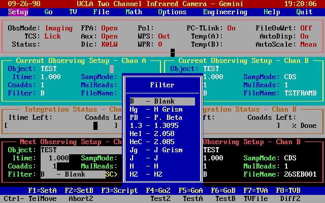
To leave the Next Observing Setup panel press the ESC key. There will be a verification/warning panel (in red) with the words "Is this correct? (Y/N)". Respond by pressing either Y for yes or N for no. Hitting Return will yield the default (Y). Repeat entire setup process for Channel B.
Go (and Abort) Commands:
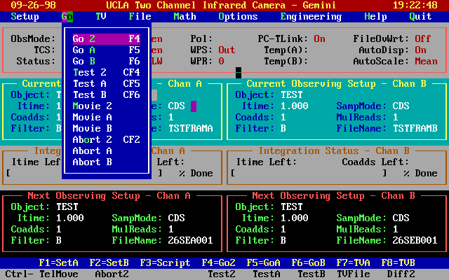
Clicking on the GO entry in the Menu Bar (or pressing G) will reveal
all of the possible options for starting and stopping integrations
(see below).
Display (TV) Commands:
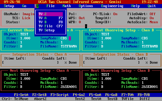
Images are automatically displayed if the AutoDisp flag is
on. Previous images can be redisplayed by using the TV menu shown
below.
Clicking on TV A or pressing F7) displays the last image in
Channel A and transfers control to the "display" monitor. To display a
previously stored image you can click on the TV File. The TV Setup
option allows you to change feature such as AutoDisp and AutoScale.
File Commands:
By clicking on File (or pressing the F key) you can access several
useful features for manipulating files, including the ability to save
a Test frame (see below).
Math Commands:
The most frequently used math operation is to form the difference of
the last two frames - to obtain a "sky-subtracted" image - so this
feature has a function key CTRL F8. Other math features can be
obtained by clicking on Math (or pressing M). Diff A and Diff B form
and display the difference of the last two frames in Channel A and B,
respectively. Diff File takes the difference of any two files. General
arithmetic operations are also available. Phot Setup allows the
magnitude zeropoints in each filter to be preset.
Options Command:
This is an important menu item which contains all of the SCRIPT
editing, checking and running features. Writing scripts is discussed in detail
elsewhere. By clicking on Escape to DOS, it is possible to exit to the
DOS prompt. Instructions are given on how to return to the Gemini
Menu.
Engineering Commands:
The next command on the Menu Bar is called Engineering. Included in
this option are commands for initializing motors (Motor Init), reading
the microswitch settings of each mechanism (Motor Read Switches) and
re-setting the transputers (PC-T Reset). It is advisable to do a PC-T Reset after
every telescope slew, as the long cables to the instrument pick up noise from the
motors and can disrupt communication between the instrument and computer transputers.
Failure to do a PC-T Reset may result in having to reboot the computer.
The Temperature Read command
is yet to be implemented. Timing Setup is an engineering feature not
available to users.
Help Commands:
Help is available on-line for several items, e.g. how to write scripts,
minimum integration times. Phone numbers and "user notes" are also
included.
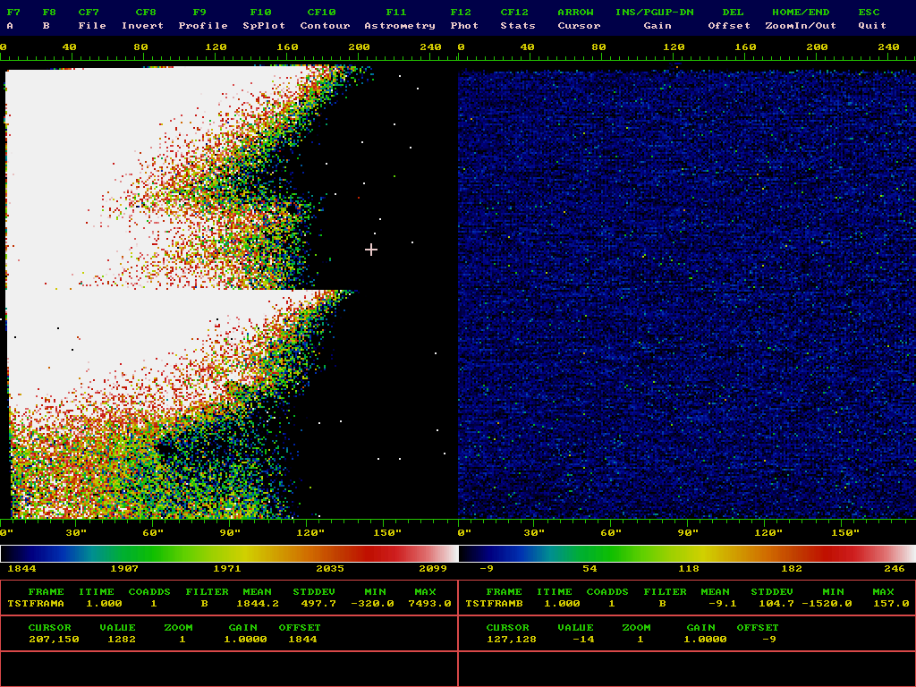
| F7 - A | transfer control to channel A |
| F8 - B | transfer control to channel B |
| CTRL F7 - File | display a file |
| CTRL F8 - Invert | invert and image (set display gain to -1) |
| F9 - Profile | display a X,Y profile centered on the cursor |
| F10 - SpPlot | display a spectral plot |
| CTRL F10 - Contour | display a contour plot of the image |
| F11 - Astrometry | perform astrometry on the image, with TCS option |
| F12 - Phot | perform photometry on the image |
| CTRL F12 - Stats | calculate statistics within a user selectable region |
| ARROWS - Cursor | move the cursor |
| CTRL ARROW | move the cursor in steps of four pixels |
| INS/PGUP-DN | change the display gain |
| DEL | change the display offset |
| HOME/END | zoom in/out on the image |
| ESC | quit display (or subdisplay) |
F7,F8
These keys place control in the A or B channel display. You may switch between these directly, or return to the main User Interface by pressing ESC. Basic information about the image is displayed below it -- filename, itime, co-add, mean, standard deviation. In addition the pixel value at the cursor is displayed, as well as the cursor coordinates. All pixel values are displayed for 1 co-add (that is the image is divided by the number of co-adds).
You may reposition the cursor using the arrow keys. Pressing CTRL and the arrow keys simultaneously will move the cursor in steps of four pixels. When control is transferred from one channel to the other, the cursor remains on the same pixel number.
The image is displayed with a default display offset and gain. Any pixel below the offset value is displayed as black. The default value depends on the parameters selected in the TV Setup menu. To change the offset, press the DEL key and enter a new value; then press ENTER. Similarly, to change the display gain, press INS, enter a new value and then press ENTER; alternately, you may increment or decrement the display gain using the PAGE UP and PAGE DOWN keys.
The image can be magnified using the HOME key, which will "zoom in" on the image, centered on the cursor. To "zoom out" press the END key. To return to the full screen, exit the Image Display by pressing ESC, and then redisplay the image using F7 or F8.
Each time control is re-transferred to the image display, the image is redrawn.
CTRL F7 -- File
Pressing CTRL and F7 together will display a file. You will be prompted for the file name. The file directory will default to the current data directory (see General Setup). The input for the filename has a limited number of characters, so you may need to change the default in order to display a file from another directory.
CTRL F8 -- Invert
Pressing CTRL and F8 together will invert the current image without changing the offset.
F9 -- Profile
This key displays an X and Y profile centered on the cursor position. The profile is tens of pixels wide in both directions.
F10 -- SpPlot
Pressing F10 will prepare to display a spectral plot. The program will prompt, in the window below the image, for the rows to be averaged into the plot and the parameters of the plot. The plot will automatically cover the entire range of displayed columns; if the image has been zoomed-in, the plot will only be across those columns.
CTRL F10 -- Contour
Pressing CTRL and F10 together will display a contour plot of the image. The plot will always cover the entire image. You will be prompted for the floor and ceiling for the plot.
F11 -- Astrometry
Pressing F11 will enter Astrometry mode. The program will prompt for two cursor positions. The distance between these positions will be calculated and displayed. Then, if the LICKTCS is in use, you will have the option of moving the telescope that distance, without exiting this mode.
F12 -- Phot
Pressing F12 will enter Photometry mode. To return to Image Display at any time, press ESC. The photometry function will calculate the flux in a box, subtract the sky from a sky box around it, and convert the flux to an apparent magnitude based on a zeropoint. The photometry box is centered on the cursor, as is the sky box.
The size of these boxes may be changed using ALT-ARROW keys. To make the "star box" bigger or smaller, press the ALT key and the UP or DOWN key simultaneously. The box is always square. To make the sky box bigger or smaller, press the ALT key and the LEFT or RIGHT arrow key simultaneously. To change the zero-point, press the INSERT key. To calculate the photometry, press the ENTER key.
All photometric information is displayed in the window below the image.
CTRL F12 -- Stats
Pressing CTRL and F12 simultaneously will enter Statistics mode. To return to Image Display at any time, press ESC. Statistics mode will calculate the mean and standard deviation in a box. To move the box use the arrow keys. (HINT: it is faster to move the cursor before entering the Statistics mode, since the box must be redrawn each time the cursor is moved). To change the size of the box (which does not have to be a square) press the ALT key and any of the ARROW keys simultaneously. To calculate the statistics, press the ENTER key.
Last modified: Mon Dec 23 12:01:45 PST 2013 by Elinor Gates
