Testing the Arrays
Testing Warm Arrays
Darks and Biases
Flat Fields
Centering and Focus
Testing Warm Arrays:
It is important that the arrays be tested warm before every cooldown. It is also advisable to test them after the instrument has been allowed to warm up to room temperature. Even if the camera has not been opened and has barely been moved, thermal cycling can affect the arrays.
Whenever the array is being run at room temperature, the photosensitive material (InSb or HgCdTe) is irrelevant. At room temperature the detector unit cells (pixels) don't act as photodiodes, but rather as conductors; the voltage output from each unit cell will just be the detector substrate voltage.
Thus, a warm array shows the response of the silicon multiplexer, not the photosensitive layer; the pattern will not look much like the flat-field or bias structure of a cold array. In addition, the response of the multiplexer changes significantly from room temperature to operating temperature, so the patter won't look like a saturated cold array, as one might otherwise expect. There will also be a large offset in the mean DC level of the output signal. In the case of the NICMOS array, this offset will place the voltage signal out of the nominal operating range of the Preamp, so all the pixels on the array will appear as "pegged" to 8192 DN.
Normally we operate the arrays in a correlated-double-sampling mode - each pixel is reset, the array is read out once, the integration time passes, and the array is read out again, with the difference between the two reads recorded as the signal. Resetting a warm unit cell has no effect, so the signal will be very nearly the same in the two readouts, and their difference will be uniformly almost zero -- only readout noise and possibly a small time-dependent bias signal. For this reason, warm arrays should always be tested in a single-sampling mode. Note that in single-sampling, there will be offsets between each output of the array (columns in the case of the SBRC).
SBRC array:
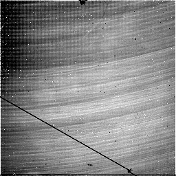
SBRC science-grade silicon multiplexers seem to be of high quality, with little pixel-to-pixel variation and almost no dead pixels. The warm array therefore shows little pattern in its signal. Slight offset differences in the preamplifier and Douglas Box introduce a column-to-column variation of a few hundred DN. There is a gradual drift (Also a few hundred DN) from the upper left to the lower right. Note that some of this drift is seen as variation up and down a column at the tens or hundreds of DN level. The offsets in the Preamp are currently set so that the mean signal is within a few hundred DN of zero, though this is subject to change; please double check with the IR Lab team if in doubt.
One important test is to check each 4 successive columns to make sure that none of the outputs are open. Autoscaling may cause one column to appears as black, even though the pixel values are reasonable (a few hundred DN, and varying from pixel to pixel). If any column is pegged at + or - 8192, this is a bad sign and may require attention.
The SBRC array does show a very strange behavior is warm; it doesn't run at slow sampling rates (slower than around 100 kHz). Gemini's sampling mode 6 (multiple-convert-per-pixel-CDS) and mode 5 (the single-sampled version of mode 6) run at 80 kHz, and thus will produce anomalous results. The array should be tested only in mode 1 (normal single-sampling) at the normal (250 kHz) sampling rate.
NICMOS array:
In general, the NICMOS multiplexer shows a lot more structure than the SBRC multiplexers. Even the science-grade NICMOS used in Gemini shows several bad pixels, and other arrays have been seen to have a lot more.
Unfortunately, the offset between a warm NICMOS array and a cold array is larger than the allowed range of Gemini's electronics. Therefore, running the array warm will just produce a signal of entirely +8192 DN. This test is still worth performing (in sampling mode 1) since a quadrant with and open connection will produce -8192 DN and a broken connection between the Preamp and the Douglas Box will also produce weird values. If for some reason it becomes necessary to change the offset on the Preamp, please notify the IR Lab team.
A more informative test is to use an oscilloscope to study the output of the array. Even though the output is still outside the ADC's range, the output of the Preamp while the array is clocking is within the range of an oscilloscope. Note that is it very important to only attach the scope to the output of the Preamp! Attaching a scope directly to the output of the array itself is dangerous.
To perform this test, use an SMA-->BNC adapter cable (a white cable, often found in the Gemini electronics tool kit). Using a grounding strap, (grounded to the Preamp box) with the DC power supplies and DE Box OFF, attach the SMA end to one of the outputs of the NICMOS Preamp. Attach the BNC end to the input of the oscilloscope. Set the scope for auto triggering, 1 sec/division and 2 V/division. Turn on the power to the oscilloscope and the DC power supplies. The output should be uniform at the preamp output rail voltage (around +5V).
Turn on the DE Box and start up the Gemini software. The software resets the array approximately once per second. You should see a burst of pixels lasting about 0.1 seconds, every second or so, on the scope output; during this reset, the array output voltage should be running from approximately -2 to -4 V. if you see the array to readout a frame (1000 co-adds of 0.5 sec integrations, single sampled -- to allow time to start the readout and observe the scope) you should see both the reset and readout of the array, back-to-back, spaced by the integration time.
On very short time scales (a few microseconds/division) you should see individual pixels; each pixel is preceded by a ~2V spike (a clock feedthrough) then a fairly uniform -1 to -3 V until the next pixel, spaced by the sampling rate (4 microseconds/pixel in mode 1). Every so often you'll see a bigger spike at the start of each row.
Repeat this process for each of the four outputs. Turn off the power when detaching and attaching the SMA to the Preamp outputs. If you don't quit the software, you will have to do a "PCT reset" from the engineering menu after you turn the DE Box off and then on.
If you have trouble getting the oscilloscope to trigger, you may have to play around with the sweep rate to see anything. Be persistent. Probably a good approach is to set the Gemini software doing thousands of 0.1 second co-adds (so that it's reading out continuously) and set the scope for very fast sweep and automatic triggering -- you'll see a confused mess if the array is working right, and a flat line if it isn't.
Darks and Biases:
Bias and dark frames are usually the first tests to be made. Select sampling mode 2 and use the shortest exposure time of 0.4 sec. Take a single co-add and display the result for both channels. Both frames should be featureless except for bad pixels and some edge effects. Take a second bias frame and use F8 to display the difference between the last two frames. The mean should be very close to zero and the standard deviation of a few DN gives the noise.
Set the Itime to 100 sec for each channel and take a DARK frame. The statistics on the display give the total counts in 100 sec (co-adds, if any, are divided out). Numbers around 1 DN/sec are typical.
Figures 2 and 3 show single-sampled and CDS bias frames for each detector.
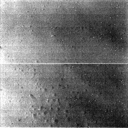
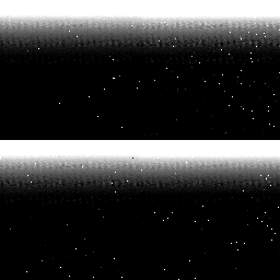
Figure 2: NICMOS Bias Frames. Top: Single-Sampling. Bottom: Correlated Double Sampling
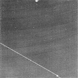

Figure 3: SBRC Bias Frames. Top: Single-Sampling. Bottom: Correlated Double Sampling
Flat Fields:
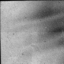
Another useful test is to take flat fields in both detectors. This may
be done either with sky flats or dome flats. See Observing Recipes for a step by step
description of the procedure. Figure 4 shows both arrays exposed to
high backgrounds.
Figure 4: Flat Field Frames. Top: NICMOS. Bottom: SBRC
Centering and Focus:
Set up on a star with the TV camera adjusted for Gemini and then move
the mirror out of the way. Select a filter pair, e.g. J and K and set
the integration time to 0.07 sec and telescope sample mode 1 (single
sampling) to prevent saturation; 10 or 20 co-adds is usually
enough. Objects of order 6th or 7th magnitude should be visible, check
centering and saturation, and then check focus.
The internal focus is easily checked by rotating the focal plane occulting spot
into the beam. The support wires should be less than 2 pixels wide.
If the Lick TV camera has been set to the nominal Gemini focus, then
focusing the telescope with the TV will bring the star in to focus for
the infrared - to first order.
A more careful focus run, in 3-5 POCO units of focus steps, should be
done taking and saving the data. The automatic "profile" routine (in x
and y) can be used on each image to determine which had the best
focus. See Observing Recipes for a
step-by-step explanation of this procedure.
Last modified: Thu Feb 15 15:49:24 PST 2007
by Elinor Gates