The Spectrograph Control Interface: hammotor_gui
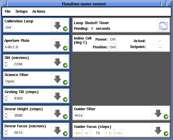
Figure 1: Hamilton Motor Controller User Interface
The software is started from the command line by typing hammotor_gui on any of the user computers.
The controller will display the current spectrograph motor positions and will allow you to either change the individual parameters, or to reconfigure using stored setups. The GUI communicates with the hardware via the dispatcher software. While the dispatchers should always be running there is a chance that they are not. In that case you will see a message such as shown in Figure 2. If you see this message, contact a support astronomer or telescope technician so they can restart the appropriate dispatcher.
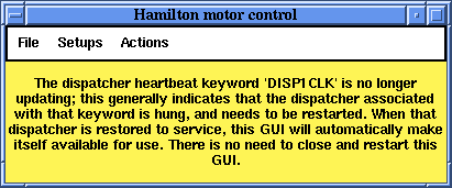
Figure 2: Hamilton Motor Controller Dispatcher Error
The spectrograph controller operates two separate galil motor controllers and the iodine cell controller, which work in parallel. Multiple stages on each controller may move at the same time. This means that if you want to change a number of items, you should not wait until one is done before requesting the next change. Make as many changes as you wish as quickly as you wish, and the controller will get it all done as soon as possible. The display will inform you of the status of each item via the icons to the right of each stage's section of the GUI.
The motors are arranged based on their order in the light path. Each motor has its own control interface within the GUI and each works in a similar way. For motors with defined positions (e.g. the Aperture Plate), click on the name of the position (e.g. 640:2.0) and it will give you a menu of available positions, as shown in Figure 3. Simply click on the desired position and it will be shown with a yellow background and a green arrow will appear immediately to the right (Figure 4). The yellow background is a warning that the motor has not yet been moved. To move the motor click on the green arrow.
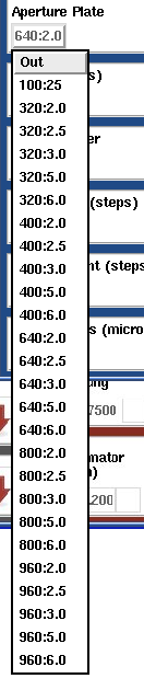
Figure 3: Aperture Plate Menu

Figure 4: Selection and Go Arrow
The Guider Focus stage has a slightly different interface where you can do moves of 1 or 5 steps in either direction instantly by clicking on the appropriate arrow. The current motor step position will be updated accordingly.
The Calibration Lamps are on a 30 minute timer once turned on. The time remaining in seconds is displayed in Lamp Shutoff Timer section. If you need the lamp to stay on for a longer period of time click the dual-arrow icon to reset the timer to 1800 seconds.
The Iodine Cell power, temperature, and position are all controlled from the Iodine Cell section. The power can either be On or Off. Its position either In or Out. Temperature setpoint is normally set to 50.0 degrees Celsius. The actual temperature of the iodine cell will be displayed only when its power is on.
The status of each motor is shown with the icons to the right of each motor name. The gray arrow indicates the direction of the light path. If the Hamilton is configured so that the light is blocked by an optical element, then a bar will appear at the head of the arrow to indicate the issue (Figure 5). Arrows downstream of that blockage will vanish from the GUI.
A green circle with a white check (Figure 5) indicates that the motor is ready and may be moved. A yellow triangle icon (Figure 6) indicates a warning that the motor has a minor issue. A red circle with white X (Figure 6) indicates that the motor is in an error state and should not (or can not) be moved. To get more information on the source of the warning or error, click on the icon and a detail panel (Figure 7) will appear.


Figure 5: Motor Moving and Lock Icons
![]()


Figure 6: Motor Warning and Error Icons
The motor detail panel gives you access to additional functions and information. In general use of the Hamilton, you should not need this panel, but it is useful in case there are problems. The state of the motor is displayed at the top of the window, along with the status icon displayed in the main GUI. During normal operations the mode should be listed as Pos. If it is in a different mode, contact a support astronomer or telescope technician. The motor can also be moved from this panel using any of the units provided. Relative moves can also be commanded. The motor and driver amplifier can also be turned on and off from the detail panel GUI, though these functions should only be done by observatory staff during engineering and troubleshooting activities.
Below the move and power functions are various status messages that can be very useful for troubleshooting, including any error messages concerning the motor.
The buttons at the bottom of the GUI are the most important for observers to be aware of. The Stop motion button will stop the stage motion. The Re-calibrate button will re-home the stage. If in doubt that a stage is positioning correctly, go ahead and re-calibrate it and set it back to the desired position. The Lock button brings up a separate GUI (Figure 8) that allows you to select the stages that need to have software control disabled for safety. The Turn motor on and Turn amplifier off buttons should only be used by observatory staff. The Close button closed the detail view GUI.

Figure 7: Motor Detail Panel
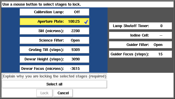
Figure 8: Motor Lock GUI
There are three menus at the top of the main GUI: File, Setups, and Actions. Keyboard shortcuts are also listed in teh menus where they are available.
The File menu (Figure 9) lets you increase or decrease the font size as well as Quit the GUI.
![]()
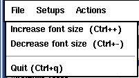
Figure 9: File Menu
![]()
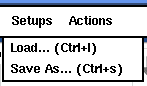
Figure 10: Setups Menu
The Setup menu (Figure 10) allows you to Load or Save motor setups. The Load... option will bring up a file browser dialog where you select your saved setup. It will load in the data and you may either move all the motors to the desired positions using Actions - Move all or move the motors using the green arrows in each motor section.
The Save As... option allows you to save the currently displayed positions to a file for future use. You do not have to move the motor to the desired position to save it in a setup, it must simply be selected and displayed in the GUI. Once the desired motor positions are displayed, click on Setups - Save As... and the Save Setup GUI will appear (Figure 11). By default all motors will be selected (yellow background) to be save in the setup. You may unselect a stage by clicking on it (it will then have a white background). Once you have selected your desired stages, click Save As... to bring up a file browser dialog to name and save your file. Please save your setup to your subdirectory in /u/user/observers/. Files saved elsewhere may be deleted or modified without notice.
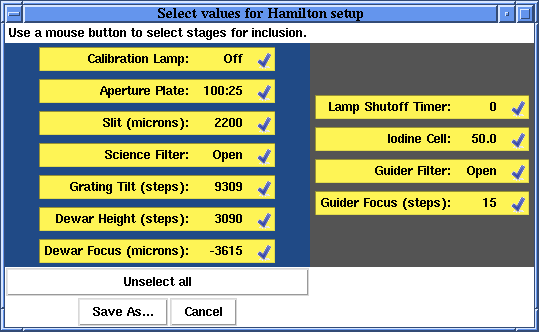
Figure 11: Save Setup GUI
![]()
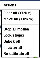
Figure 12: Actions Menu
The Actions menu (Figure 12) has the following options:
- Clear all (Ctrl+c) -- Clear any desired positions from the GUI that don't match the actual positions of the motors.
- Move all (Ctrl+m) -- Move all motors whose desired positions don't match the actual positions.
- Stop all motion -- Stop all stage motor motion.
- Lock stages -- Lock out software control of selected stages for safety while staff members work on hardware. This brings up the Lock GUI (Figure 8) where you can select which stages to lock out. You must supply a reason for the lockout. The lockout icon is shown in Figure 5.
- Unlock all -- Unlocks the software control of all locked out stages. For safety reason do not unlock a stage unless you have consulted with the person(s) working on the hardware.
- Initialize all -- Initialize software communication between the dispatchers and the Hamilton motor control GUI. This usually only has to be done if all (or most) motors show yellow warning icons (as happens when the spectrograph motor controller is first turned on). If a stage is not calibrated, the software will calibrate the stage when initialize all is selected.
- Re-calibrate all -- Re-calibrate (i.e. home) all the motors. This function can take a while, so should only be done as needed (e.g. when the motor controller is first turned on). Please make sure no one is working on the instrument before re-calibrating all the motors, as injuries could occur. Individual motors can be re-calibrated from the Detail Panel (Figure 7).
Support Astronomers (sa@ucolick.org) Last modified: Fri Feb 11 15:43:12 PST 2011