Hardware Overview
The Hamilton Spectrograph may be used with either the Shane 3-m Telescope or the Coudé Auxiliary Telescope (CAT). When using the 3-m, the light enters the slit room in an f/36 beam (f/38 in the 5-mirror configuration) from the Shane's hollow polar axle. When using the CAT, the light enters the slit room through a portal in the ceiling. A flat mirror -- CAT #5 mirror (not shown here) -- is swung into place about 18 inches ahead of the aperture plate, directing the f/36 beam onto the Hamilton's optical path. Downstream of this flat mirror, the CAT lightpath is identical to the 3-meter's and the two beams are indistinguishable to the spectrograph. However, the 3-m and CAT platescales at the aperture plate do differ.
The beam crosses the slit room and comes to a focus at the aperture plate. The aperture plate's polished surface is slightly tilted so that light not passing through it to the spectrograph is reflected to the acquisition and guide TV.
(Click image for full-size drawing in a new window.)
The slit room also contains the arc and flat field lamps and the following optional equipment: image rotator, iodine cell, and photon integrator.
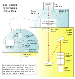
The focused light passes through the aperture plate to the filter wheel and shutter to enter the camera room. The camera room contains the fixed optics of the spectrometer. Refer to Figure 1 for a schematic of the Hamilton Spectrograph Optical Path.
The light then passes through the spectrograph's fixed optics that lie between the entrance slit and the detector. In lightpath order they are:
- Collimator: an off-axis parabolic mirror (i.e., the mirror is made from an off-axis portion of a larger parabolic mirror) which makes parallel the diverging beam from the slit, and at the same time turning it 11-degrees off its original optical axis, directing it to the echelle grating.
- Echelle Grating: a large, coarse-ruled (31.5-lines/mm) reflection grating, meant to be operated at high order; the echelle may be remotely rotated to adjust the position of the spectral format on the CCD detector.
- Cross Disperser: two large prisms (UBK glass) which separate the overlapping spectral orders coming from the echelle, spreading them perpendicular to dispersion, into a nearly parallel, ladder-like format.
- Schmidt Camera: a four-element camera, consisting of an aspheric corrector, folding flat mirror, spherical mirror, and field flattener, which refocuses the parallel, dispersed beam onto the CCD detector.
The dispersed light is detected with one of three CCDs, referred to as Dewar 4, Dewar 6, or Dewar 8. Refer to CCD Characteristics for details of the differences between the detectors to select which one is best for your program.
Support Astronomers (sa@ucolick.org) Last modified: Tue Feb 15 14:12:40 PST 2011