User's Guide to the Hamilton Spectrograph


Table of Contents


Introduction
Quick Reference
Hardware
CCD Characteristics
Apertures
Grating Tilt & Dewar Height
Filter Wheel & Shutter
Calibration Sources
Photon Integrator
Image Rotator
Iodine Cell & Slit Room Controller
Guide Camera & Filter Wheel
Software
Data Taking System
Hamilton Motor Controller
Showmidpoint
Eventsounds
Hamilton Focus
More Info:
Spectral Format
Navigating the Spectrum
Table of Orders
Setup Procedures
Checklists
Observing Hints
Throughput

Data Archive
Mt. Hamilton Homepage

Calibration Sources

A quartz lamp, usually called the 'polar quartz,' mounted on the wall opposite the slit, where the telescope's polar axle enters the slit room, provides a continuum source for flat fielding. When not in use, it is stowed to one side. Selecting the lamp from spectrograph motor control program hammotor_gui, automatically slides it into the lightpath and turns it on.

A thorium-argon hollow cathode line lamp for wavelength calibration is mounted above and behind the slit (additional lamps, such as iron or mercury, can be mounted if necessary - please consult a support astronomer well in advance of your run for availability and feasibility of installation). The arc lamp light is directed into the spectrograph via a turning mirror that slides into place above the slit when a line lamp is selected in hammotor_gui.

hammotor_gui's lamp menu is shown in Figure 1. If a lamp appears to be weak or burned out, contact a member of the staff.


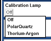
Figure 1: Lamp Selection Menu

N.B. In order to protect expensive lamps, the light sources are on timers that will turn them off automatically after about 30 minutes. A lamp timer is displayed in hammotor_gui (see Figure 2) and may be reset to 1800 seconds by pressing the circular arrow icon. Please turn off lamps when you are finished using them.


Figure 2: Lamp Timer GUI

The performance and output of calibration lamps varies. Over the life-cycle of a particular lamp, intensities (e.g. of spectral lines) may decrease or increase with time until one, or more, of the constituents of the lamp ultimately decays. Decay can occur over a noticeable time interval or may be instantaneous.

In the event of the decay of an existing calibration lamp, attempts shall be made to install a like-for-like replacement from stock spares, sufficient to generate spectra which can provide overall calibrations consistent with the preceding lamp. However, design, suppliers and costs of replacement lamps evolve. There is no guarantee that replacement calibration lamps shall be identical to their predecessors. Replacement lamps may differ from their predecessors in important ways (e.g. manufacture, geometry, relative percentages of chemical composition), all of which affect the characteristics of resultant spectra. Therefore, during the life-cycle of a particular calibration lamp and following the replacement of a calibration lamp, intensities (e.g. of spectral lines) may differ markedly.

Designers of automated reduction procedures are advised to generalize their routines to accommodate changes in intensitie (e.g. spectral lines; peak wavelength), in preference to fixing analyses to one contemporaneous set of reference spectral features.


Support Astronomers (sa@ucolick.org)
Last modified: Wed Feb 22 17:53:00 PST 2012