Photon Integrator
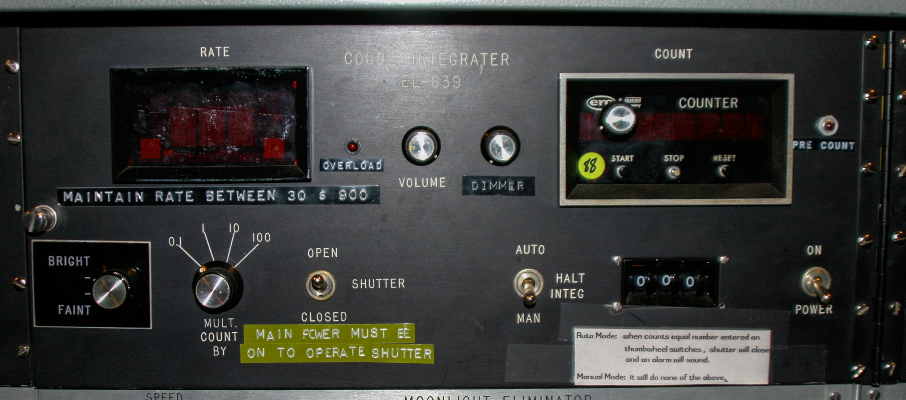
Figure 1: Integrator Control Panel
- Make sure the "Dimmer Power" and "Shutter" switches are on (i.e. toggle switches are up, see Figure 2 below).
- Turn on the integrator. The power switch is located on the lower right of the integrator panel (see Figure 1).
- Check the shutter, brightness, and multiplier dials to make sure they are properly set for your program. The usual settings are one step above "Faint", 0.1 multiplier, and Open shutter. Rarely are other settings necessary.
- Before turning on the PMT power, make sure the voltage dial on the right is set to zero (Figure 3).
- Turn on PMT power supply. Slowly turn the dial to 705. This corresponds to a reading of ~137 on the display (Figure 4).
- Pull the plunger (Figure 5) for the chopper to start it rotating (you should be able to hear the faint whir of its motion). You should also hear beeps from the integrator panel for each count detected by the PMT.
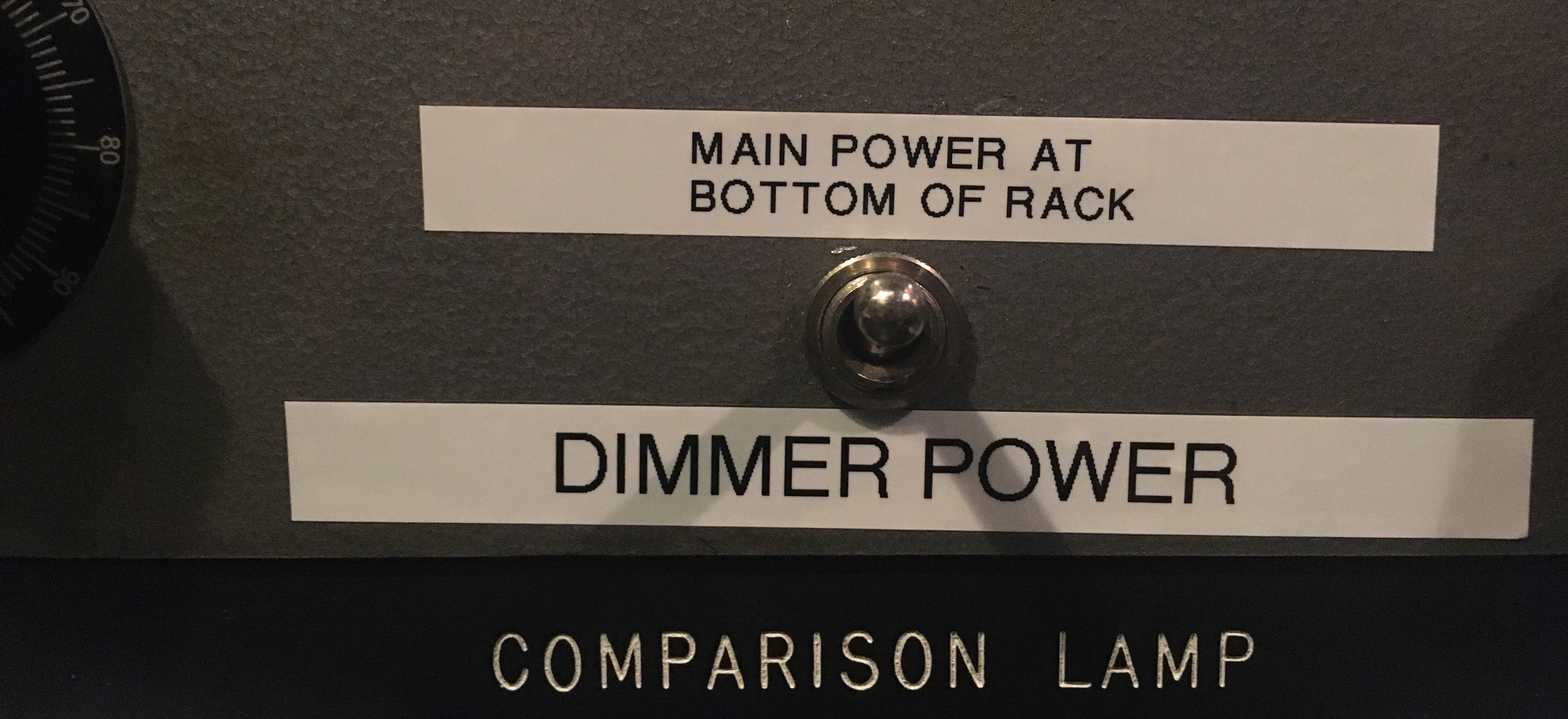

Figure 2: Dimmer Power and Shutter switches should always be on (toggle switch in up position).

Figure 3: PMT Power Supply, voltage dial set to zero.

Figure 4: PMT Power Supply, voltage dial set to 705.

Figure 5: Integrator Chopper Plunger.
When done with the integrator at the end of the night, shut it down in the following procedure.
- Push in the plunger. This ensures that the chopper is parked out of the way of the slit and will not block the light for future observers not using the integrator (Figure 5).
- Turn the PMT dial down to zero (Figure 3).
- Turn off PMT power supply (Figure 3).
- Set Shutter switch on Integrator Panel (Figure 1) to Closed.
- Turn off integrator (Figure 1).
The photon integrator hasn't been fully characterized, but preliminary testing (Feb 2021) gives the following count rates on the detector:
5.5 DN/pix/PMT count @ 5500A for a B-V=0.0 star
9.5 DN/pix/PMT count @ 7500A for a B-V=0.0 star
with the standard settings. Redder stars appear to generate higher
DN/pix/PMT count and bluer stars fewer at the sampled wavelengths,
but has not yet been calibrated.
Support Astronomers (sa@ucolick.org) Last modified: Mon Feb 22 19:01:29 PST 2021